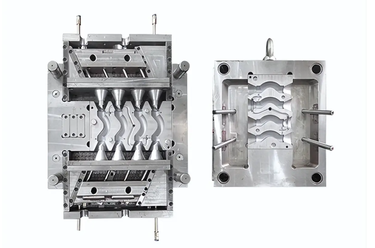
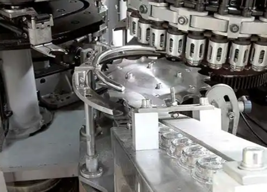
Venting is crucial, especially for thin - walled products and areas far from the gate. For small or precision parts, venting is also essential. It prevents surface burns, short shots, eliminates product defects, and reduces mold contamination.
The main functions of venting are two - fold: expelling air in the mold cavity when injecting molten material and removing gases generated during material heating.
Adequate venting can be judged by injecting molten material at the highest injection rate without burn marks on the product.
There are various venting methods, but each must ensure that while venting, the vent size prevents material from flowing into the vent and also guards against blockages.
Measured from the inner surface of the mold cavity towards the outer edge, for vent sections longer than 6 - 12 mm, the vent height should be increased by about 0.25 - 0.4 mm. Also, too many vents are harmful as high clamping pressure on non - vented areas of the mold parting surface can cause cold flow or cracking of the mold material.

Besides venting on the parting surface, vents can be set at the end of the runner in the gating system or by leaving gaps around ejector pins. However, improper depth, width, or location of vents can create burrs that affect product aesthetics and accuracy. So, the gap around ejector pins should be sized to prevent burrs.
For gears, where even the slightest burr is unacceptable, venting methods include thoroughly purging gas in the runner and shot - peening the mating surfaces of the parting line with 200 - grit silicon carbide abrasive. The vent at the end of the runner in the gating system, mainly at the end of the sub - runner, should have a width equal to the sub - runner width, and its height varies with the material.
For molds of products with complex geometries, venting layout is best determined after several trial runs. The integral structure in mold design has the major drawback of poor venting.
For integral mold cavities and cores, venting methods include using cavity grooves or insert installation sites, side insert joints, making parts helical, and installing slotted strips or creating process holes longitudinally. When venting is extremely difficult, a split - and - assemble structure can be adopted. If there are hard - to - vent corners in the mold, and without affecting product appearance and accuracy, the mold can be modified for split - and - assemble processing, which not only facilitates venting but also eases machining and maintenance.
Venting is more critical for thermosetting materials than thermoplastic ones.
First, vents should be set in the sub - runners in front of the gates. The vent width should be equal to the sub - runner width, with a height of 0.12 mm. Vents should be around the mold cavity, spaced 25 mm apart, 6.5 mm wide, and with a height of 0.075 - 0.16 mm depending on material fluidity (lower values for softer materials).

Ejector pins should be enlarged as much as possible. In most cases, 3 - 4 planes 0.05 mm high should be ground on the cylindrical surface of the ejector pins along their length using a fine - grit grinding wheel. The end face of the ejector pin should be chamfered by 0.12 mm so that if burrs form, they adhere to the product.
Proper venting can significantly reduce injection pressure, injection time, holding pressure, and clamping pressure, making plastic part molding easier, thus improving production efficiency, reducing costs, and lowering machine energy consumption.
Venting can be achieved through multiple methods, not just vent grooves:
Vent Groove Venting: For large and medium - sized plastic part molds, vent grooves are often used. They are usually set on the concave die side of the parting surface, at the end of the melt flow. The width is about 3 - 5 mm, depth less than 0.05 mm, and length about 0.7 - 1.0 mm.
Parting Surface Venting: For small molds, the parting surface gap can be used for venting, with the parting surface at the end of the melt flow.
Joint Gap Venting of Assembled Parts: For combined concave dies or cavities, the joint gaps can be used for venting.
Ejector Pin Gap Venting: Utilize the clearance between the ejector pin and the template or core, or intentionally increase this clearance.
Powder - Sintered Alloy Block Venting: Powder - sintered alloy, made of spherical alloy particles, is porous and allows gas passage. Place such an alloy block at the venting location, ensuring the bottom vent hole diameter is not too large to avoid deformation under cavity pressure.
Vent Well Venting: Set a cavity outside the confluence of the plastic melt to allow gas to escape, achieving good venting results.
Forced Venting: Install vent rods in gas - trapped areas. This method has good venting effects but leaves rod marks on the plastic part, so the vent rod should be placed in a concealed location.


